Measurement
By observing the flow of fluid into the container on the uroflowmetry device, the load cell registers corresponding changes in its output value. The load cell can be precisely calibrated to accurately reflect the weight applied to the uroflowmetry device. Utilizing the known density of the fluid, this calibrated output can subsequently be employed to determine the precise volume of the fluid being measured.
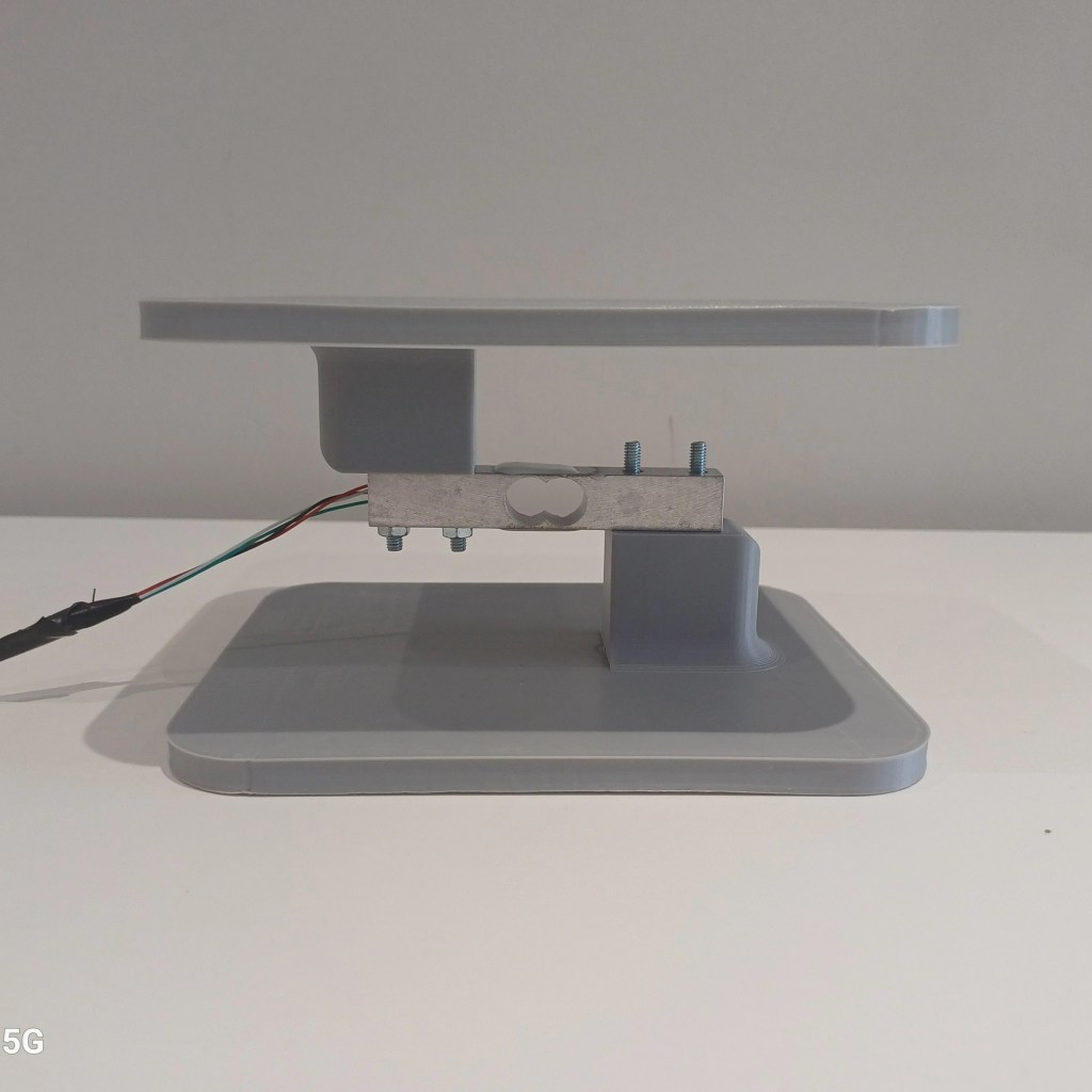
Design
The uroflowmetry device is composed of essential components including a load cell, two plates, and two spacers that ensure the secure positioning of the load cell. To maintain stability, it is crucial for the two end plates to remain parallel to each other. Additionally, the end plates need to provide ample surface area to accommodate the fluid collection container while effectively preventing any unwanted movement. The load cell must be rated for 0-3/5kg.

To establish a connection between the load cell and the control device, the leads extending from the load cell can be conveniently attached to a 4-core wire. It is important to ensure that the wire does not exceed a length of 1.5m to maintain optimal signal integrity. For seamless integration with the control device, a DIN connector can be securely affixed to the opposite end of the wire, facilitating a reliable and efficient connection between the load cell and the control device.
Manufacturing
- Prepare the supporting material
- Prepare the rigid material to be used as spacers for the load cell
- Prepare the rigid material for the base and platform
- Prepare the load cell
- Connect the leads to a 4-core wire
- Solder a DIN connector to the end of the 4-core wire
- secure the loadcell to the base, spacers and platform
Signal Processing
Once the load cell is connected to the power supply and main board the analog changes in voltage can be measured via the DIN connection. The main board routes the analog uroflowmetry signals through an amplifier and analog-to-digital converter, this provides the digital measurements required by the software. The software then calculates the rate of change of volume, providing the voiding flow rate.
Component selection and manufacturing tips
- Ensure that the base and platform plates are rigid
- Ensure the spacers do not touch the strain gauges on the loadcell
- Check the spacing of holes on both ends of the load cell
- Check the bolt diameter required by both ends of the load cell
Validation testing
Validation testing can be performed once the previous steps have been completed and the system controller has been manufactured.
